Describe a 4 Input and Gate Using Vhdl
Data flow and Algorithmic. Module OR_2_behavioral output reg Y input A B.

Lesson 3 Multiple Input Gates In Verilog And Vhdl Youtube
When used in this context the Arty A7 becomes the most flexible processing platform you could hope to add to your.
. In this VHDL code the circuit is described in RTL Resister Transfer Level This VHDL code is compiled and it generates Netlist at Gate level. It was designed specifically for use as a MicroBlaze Soft Processing System. And one output ports of 7-bit.
This is usually done by a digital designer and is similar to a high-level computer programmer equipped with digital electronics skills. Transmission gate primitives include both buffers and inverters. The logic equation of an XOR Gate is.
The trap-and-release phenomenon as eqn 9 reveals occurs more often at low frequencies and therefore flicker noise is also called 1f noise. Enter the email address you signed up with and well email you a reset link. The compiler converts high-level VHDL code in RTL to Gate Level.
Another way to describe a digital circuit or system is by using a suitable HDL such as VHDL 9 10. In the gate instantiation syntax shown below GATE stands for either the keyword buf or NOT gate. The above statement models a xor gate having a propagation delay of 10 nanoseconds.
Verilog standardized as IEEE 1364 is a hardware description language HDL used to model electronic systemsIt is most commonly used in the design and verification of digital circuits at the register-transfer level of abstractionIt is also used in the verification of analog circuits and mixed-signal circuits as well as in the design of genetic circuits. He is passionate about. Instead a behavioral description is developed to analyze the design in terms of functionality performance and other high-level issues using a Hardware Description Language such as Verilog or VHDL.
Not buf bufif0 bufif1 notif0 notif1. Optimization is done for better speed and less space. VHDL Code for Synthesizing XOR Gate.
Again we begin by declaring module setting up identifier as OR_2_behavioral and the port list. The behavioral level can be further divided into two kinds of styles. Verilog code for OR gate using behavioral modeling.
Not n outout inverter. In this case the port list includes the output and input ports. As the VHDL compiler is a software and simulating the hardware so it really cant simulate the exact same behavior.
Y XY X Y Behavior Sequential Modeling. Verilogerilog Coding Style Coding Style REF. Reuse Methodology Manual For System-ON-A-Chip Design Third Edition 2002 CIC Training Manual.
An example VHDL description for each of the basic logic gates using the built-in logical operators in VHDL is shown in Figure 510. Arty A7 Reference Manual The Arty A7 formerly known as the Arty is a ready-to-use development platform designed around the Artix-7 Field Programmable Gate Array FPGA from Xilinx. At the same time this will also be the first real life test of NE555 logic as the MCPU is a bit too complex and large to detect basic errors with the logic style.
Buf n output buffer. The dataflow representation describes how data moves through the system. This describes the operation of the circuit or system at different levels of design abstraction.
The XOR gate produces a HIGH 1 output when one of its two input is high 1 LOW 0 otherwise. One input ports of the 4-bit and second input port of 1 bit for enable. Grtgrsteruegwertfwt rgrdsydrgd ryey ryhgey.
The above identifiers are called basic identifiers. This Netlist is further optimized to get optimized Netlist again at Gate Level. Fx f 1 x f 2 x f 3 x f 4 x T and gx are the nonlinear terms in column vector forms that you derived from the Lagrangian method F c.
The VHSIC Hardware Description Language VHDL is a hardware description language HDL that can model the behavior and structure of digital systems at multiple levels of abstraction ranging from the system level down to that of logic gates for design entry documentation and verification purposesSince 1987 VHDL has been standardized by the Institute of Electrical and. They have single input and one or more outputs. An important attribute of flicker noise is its inverse dependence on the area of the transistor which suggests that to decrease the 1f noise the W L of the transistor must be maximized.
This style of modeling makes use of the behavior or the algorithm of the operation. Well describe the functionality of the dice in VHDL and use PCBFlow to synthesize the digital description into an implementation based on NE555 logic. VHDL allows one to describe a digital system at the structural or the behavioral level.
In addition P-channel-metal-oxide-semiconductor PMOS.
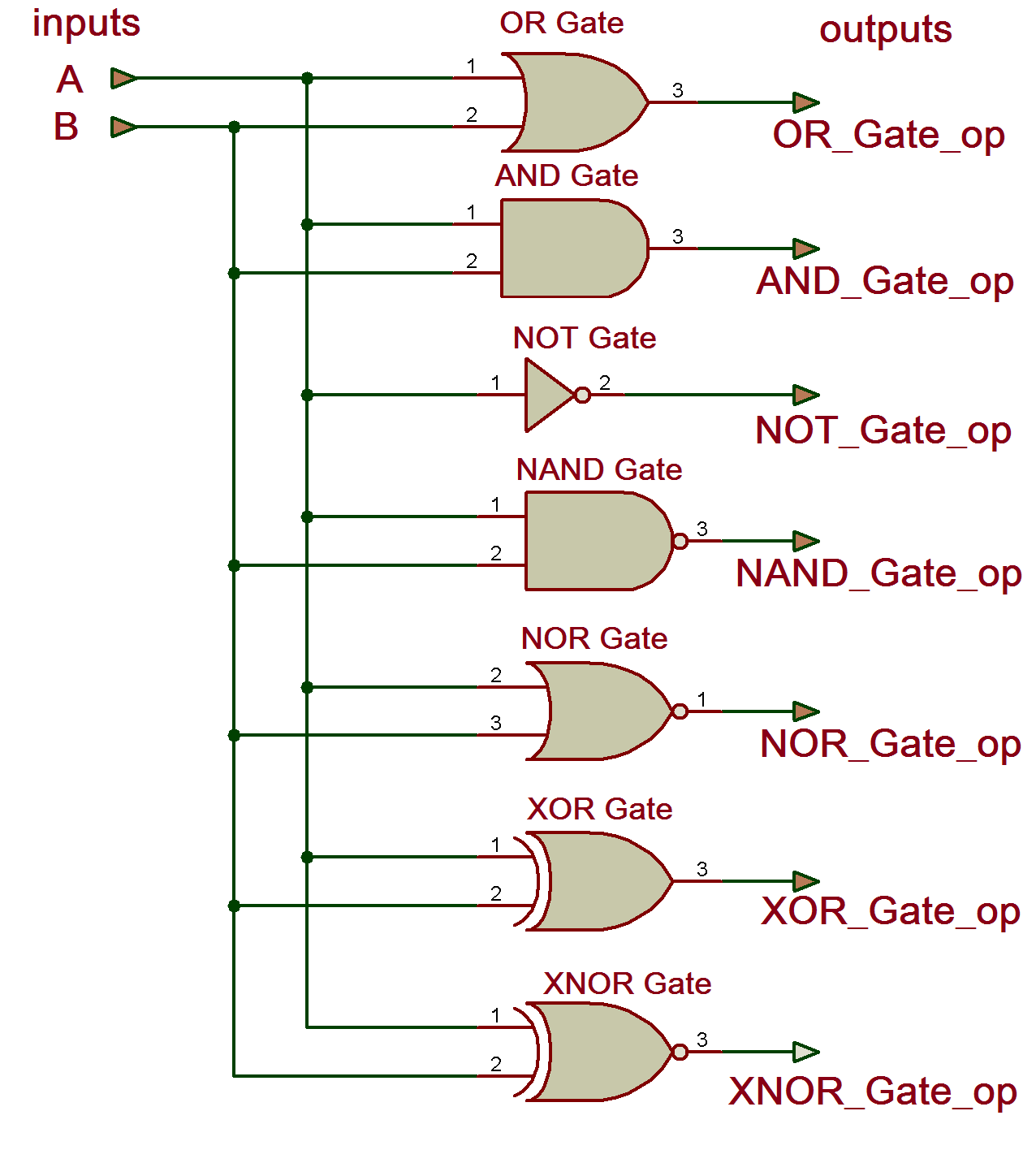
Vhdl Tutorial 4 Design Simulate And Verify All Digital Gate And Or Not Nand Nor Xor Xnor In Vhdl

Vhdl Tutorial 4 Design Simulate And Verify All Digital Gate And Or Not Nand Nor Xor Xnor In Vhdl

Implementation Of Basic Logic Gates Using Vhdl In Modelsim


Comments
Post a Comment